MEASURE AND MOVE
Introduction
PCB layout frequently requires knowing the exact distance between two objects and then positioning one of them at a specific offset from the other. These tasks arise throughout the design process:
- Checking mechanical clearances: connector to board edge, mounting hole spacing, component bodies to board edges for case aperture alignment.
- Verifying rework access: ensuring there is space for a soldering iron tip between components.
- Comfort clearances beyond DRC minimums for specific signals, parts, or thermal zones.
- Heatsink clearance to neighbouring objects, with space for spring clips or thermal pads.
- Fiducial placement relative to board edges and components for vision placement systems.
- Spacing between electrolytics, and checking nearby silkscreen is not obscured.
- Testpoint spacing relative to other testpoints, component bodies, or board features.
- Routing space assessment between objects.
- Precise silkscreen placement relative to pad edges or other silkscreen features.
The DRC system enforces minimum distances, but it cannot handle user-specified clearances, object-specific requirements, or mechanical fitting constraints. Measure Mode provides a dedicated tool for measuring the distance between any two objects on the layout and, when required, re-positioning one of them to achieve a precise spacing.
Measure Mode
Measure Mode is a dedicated editing mode for measuring distances between objects. Select it from the mode toolbar, below the 2D graphics modes, or use the keyboard shortcut if one has been assigned. When you enter Measure Mode, the normal object selector panel is replaced by the Measure Panel, and the cursor behaviour changes to snap to object edges and boundaries. All other editing modes (placement, routing, etc.) are suspended until you leave Measure Mode by selecting a different mode.
To make a measurement:
1) Enter Measure Mode. The Measure Panel appears in place of the object selector.
2) Left click on the first object (object A). The cursor snaps to the nearest edge or feature of the object.
3) Move the cursor towards the second object (object B). As you move, a green arrow is drawn from the snap point on object A to the current cursor position, and the Measure Panel updates with live distance readings.
4) Left click on the second object (object B). The cursor snaps to its nearest edge or feature, the green arrow locks in place, and the Measure Panel shows the final distances.
Once a measurement is established, the Measure Panel displays the total, horizontal, and vertical distances and enables the Move controls. The measurement persists on screen until you start a new measurement or leave the mode.
You do not need to click precisely on the exact point you want to measure from. The snap system captures the geometric shape of each object, and the measurement modes (described below) can then calculate the closest points, the nearest edge-to-edge distance, or an aligned distance between the two shapes.
Snapping in Measure Mode
In Measure Mode, the cursor snaps to object edges and boundaries rather than just centres. The snap system recognises:
- Pad edges, centres, resist openings, drill holes, and slotted or offset holes in pad-stacks.
- Trace edges, centres, and vertices.
- Component centres and courtyard boundaries.
- Zone edges.
- 2D graphic edges, centres, and vertices.
- Labels.
- Room boundaries.
When the cursor is near an object, a snap hint appears in the status bar identifying what you are snapping to. The cursor changes to a crosshair with a marker when snapped to an object, and to a forbidden symbol if no valid snap target is in range.
The snap operates on all visible layers. If you need to constrain measurement to a specific layer, hide the layers you do not want to snap to before measuring.
The Measurement Arrow
The measurement is displayed as a green arrow drawn between the two measured points, with a perpendicular bar at the base (object A end) to indicate the direction of measurement. The arrow scales with the current zoom level so it remains visible at any magnification.
The Measure Panel
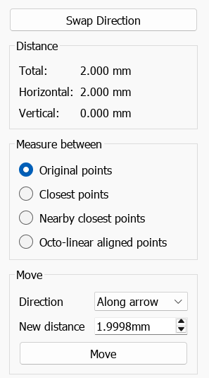
The Measure Panel, shown with an active measurement between two objects. This panel replaces the object selector when Measure Mode is active. The Move group adapts to single-object measurements, in which case New Distance is replaced by Move By.
Swap Direction
The Swap Direction button reverses the direction of the measurement, exchanging object A and object B. This is useful when you want to move the other object, since the Move function always acts on the object at the arrow tip (object B).
Distance
The Distance group displays three values:
- Total: the straight-line distance between the two measured points.
- Horizontal: the horizontal component of the distance.
- Vertical: the vertical component of the distance.
All three values update in real time as you move the cursor (before clicking the second point) and when you change the measurement mode. The values are shown in the current board units.
When polar co-ordinates are active, the Horizontal and Vertical labels change to Radial and Circumferential. See Measuring and Moving in Polar Mode below for the rest of the differences.
Measure Between
The Measure Between group provides four radio buttons that control how the distance is calculated from the two snapped shapes. In all modes, the measurement uses the full geometric shape of each object (not just the click point), so the result accurately reflects the physical geometry of the objects on the board.
Closest Points is unavailable when both ends of the arrow snap to the same feature, since the closest distance from a shape to itself is zero. Note that the test is on the snapped feature, not on the object: two pads on one component are different features, so Closest Points stays available when you measure between them. Nearby Closest Points is never disabled. The arrow remains a valid measurement in either case; it just describes a dimension within a single object rather than a clearance between two objects. The Move group also adapts to single-object measurements: see Moving Objects to a Specified Distance below.
Original Points
Measures the distance between the exact points where you clicked (after snapping). The arrow runs directly from the snap point on object A to the snap point on object B. This is the default mode and is useful when you want to measure between two specific features, for example pad centre to pad centre, or a trace vertex to a board edge corner.
Closest Points
Calculates the absolute shortest distance between the two object shapes, regardless of where you clicked. The arrow repositions to connect the two nearest points on the respective shapes. This gives the true minimum clearance between the objects, equivalent to the gap that a DRC check would report. Use this mode when you need to verify the physical clearance between two objects, for example the gap between two component courtyards or between a pad edge and a nearby trace edge.
Because Closest Points considers the entire extent of each object, the arrow may reposition to a point that is off screen, particularly when one of the objects is large (such as a power plane zone or a long board edge). If the arrow seems to disappear after switching to this mode, zoom out to find it. The same can occasionally happen with Nearby Closest Points, although it is much less likely since that mode constrains the result to the neighbourhood of your original clicks.
Nearby Closest Points
Similar to Closest Points, but constrains the result to stay near the points where you clicked. If the absolute closest points are far from your click positions (for example on the opposite side of a large component), this mode finds the shortest distance in the local neighbourhood instead. This is the most practical mode for edge-to-edge measurements where you want the minimum distance in a specific area of the objects.
Nearby Closest Points is often the best general-purpose mode. It gives you the edge-to-edge clearance in the region you are looking at, without jumping to a different part of the object where the shapes happen to be closer.
Octo-linear Aligned Points
Constrains the measurement to the nearest of eight compass directions: North, South, East, West, and the four 45° diagonals. The arrow is aligned to whichever of these compass directions is closest to the line between the click points. This is the same eight-way alignment used in transit and underground maps, and it is also the natural geometry of most PCB layouts: board outlines are typically rectangular, traces follow L45 (orthogonal plus 45°) routing, mitres are at 45°, and component bodies are placed at 0° or 90° rotation. In all of these cases the octo-linear directions coincide with the natural perpendiculars and parallels of the design.
Use Octo-linear when you want a measurement that aligns with the layout grid: perpendicular drops to horizontal or vertical board edges, distances along a 45° trace direction, the horizontal or vertical component of an offset between axis-aligned features, or any measurement you intend to express as "this much horizontally and this much vertically".
Octo-linear alignment is defined by the board co-ordinate system, not by the geometry of either object you click on. For axis-aligned and L45 features (the usual case) this happens to coincide with perpendicular-to-source, but it is not guaranteed. If the source feature is rotated to an arbitrary angle (for example, a chamfered board edge that is not at 45°, or a board outline drawn at 30° for some mechanical reason, or a component placed at 17° rotation), the octo-linear arrow will not be perpendicular to it and the distance shown will not represent the perpendicular clearance. For perpendicular-to-edge measurements on arbitrary-angle features, use Closest Points or Nearby Closest Points instead: these find the geometric shortest distance regardless of the orientation of either feature.
If the two click points do not lie close to any octo-linear alignment, the mode falls back and no measurement is shown.
Measuring and Moving in Polar Mode
When the co-ordinate display is switched to polar with the Toggle Polar Co-ordinates command (default key Z) the Measure Panel follows it, and the whole measure-then-move workflow becomes angular. Everything is referred to the current origin, so set a false origin at the centre of the circle you are working to before you start.
What Changes on the Panel
- The Horizontal and Vertical readouts in the Distance group become Radial and Circumferential.
- The fourth Measure Between radio button, Octo-linear aligned points, becomes Polar-aligned points. It constrains the arrow to a pure radial or pure circumferential line, in the same way that octo-linear constrains it to the eight compass directions.
- The Direction options in the Move group become Radial and Circumferential in place of Horizontally and Vertically. Along arrow reads Straight-line when the arrow itself is circumferential, as a reminder that the move follows the chord rather than the arc.
Moving by Angle
Where the measurement is angular the New Distance spin box is replaced by an angle spin box reading in degrees. It is captioned New angle when the arrow connects two different objects, and Rotate by when both ends land on the same object, mirroring the New Distance and Move By behaviour of cartesian mode exactly.
Also Rotate Object
An Also rotate object checkbox appears alongside the angle spin box. Leave it clear and the object is carried round to its new angular position while keeping its original orientation. Tick it and the object is rotated about the origin instead, so it turns to face outward as it moves. Ticking it is what you want when laying out a ring of connectors, LEDs or mounting holes that must each point away from the centre.
Polar mode is at its most useful for circular arrangements: set a false origin at the centre, measure the radius of the first part, then use Rotate by with Also rotate object ticked to step successive parts around the circle. Where you need many copies at a fixed angular pitch, the radial variant of Replicate is quicker.
See Also:
Moving Objects to a Specified Distance
Once a measurement is established, the Move group in the Measure Panel becomes active. The behaviour of the Move group depends on whether the arrow connects two different objects or two points on the same object.
Moving Between Two Objects (New Distance)
When the arrow connects two different objects, the Move group displays a New Distance spin box. The Move function repositions object B so that it lies at the entered distance from object A. This is the standard measure-then-move workflow used to set a precise gap, offset, or alignment between two physical features.
1) Make a measurement between object A and object B as described above.
2) In the Move group, choose a direction from the Direction dropdown:
- Along arrow: moves object B along the line of the measurement arrow.
- Horizontally: moves object B in the X direction only.
- Vertically: moves object B in the Y direction only.
These are the cartesian options. In polar mode the last two read Radial and Circumferential instead, as described under Measuring and Moving in Polar Mode above.
3) The New Distance spin box is pre-populated with the current distance for the selected direction. Edit this value to the distance you want.
4) Click the Move button. Object B is repositioned so that the distance between the two objects matches the new value.
The measurement updates automatically after the move, so you can verify the result immediately and make further adjustments if needed.
The move operation is recorded in the undo history. Press CTRL+Z to reverse a move if the result is not what you intended.
How the Move Applies
The Move button repositions the object at the arrow tip (object B). The displacement is the difference between the new distance and the current distance, applied in the chosen direction.
- Along arrow: the object moves along the vector from A to B by the required delta.
- Horizontally: the object moves left or right to achieve the new horizontal distance.
- Vertically: the object moves up or down to achieve the new vertical distance.
If the measurement arrow points to a pad that belongs to a component, the entire component is moved (not just the individual pad). If the pad belongs to a zone, however, the pad itself is moved independently.
The Horizontally and Vertically options are disabled when their respective component of the current measurement is zero (i.e. the two objects are already perfectly aligned in that axis).
Swapping Direction Before Moving
By default, the Move function repositions the object at the arrow tip (object B). If you want to move the other object instead, click Swap Direction before entering the new distance. This reverses the arrow so that the other object becomes the target for the move.
Always check which object is at the arrow tip before clicking Move. A common mistake when zoomed in closely is to move the wrong object. For example, if the arrow runs from a mounting hole to the board edge, clicking Move will reposition the entire board outline, potentially creating DRC errors and disrupting other positioning across the board. In this case you should click Swap Direction first so that the mounting hole (the smaller, local object) is the one that moves.
A locked object cannot be moved. If the object at the arrow tip is locked, or is a pad or a trace belonging to a locked component, the Move button reports that the position is locked and nothing happens. Unlock the object first, or click Swap Direction and move the other one instead. See Locking an Object.
Moving a Single Object (Move By)
When both ends of the arrow land on the same object (for example, you have measured the pitch between two pads on a component, or the width of the board outline, or the length of a single trace segment), the Move group changes mode. The New Distance spin box is replaced by a Move By spin box, and the Move function offsets the entire object by the entered amount.
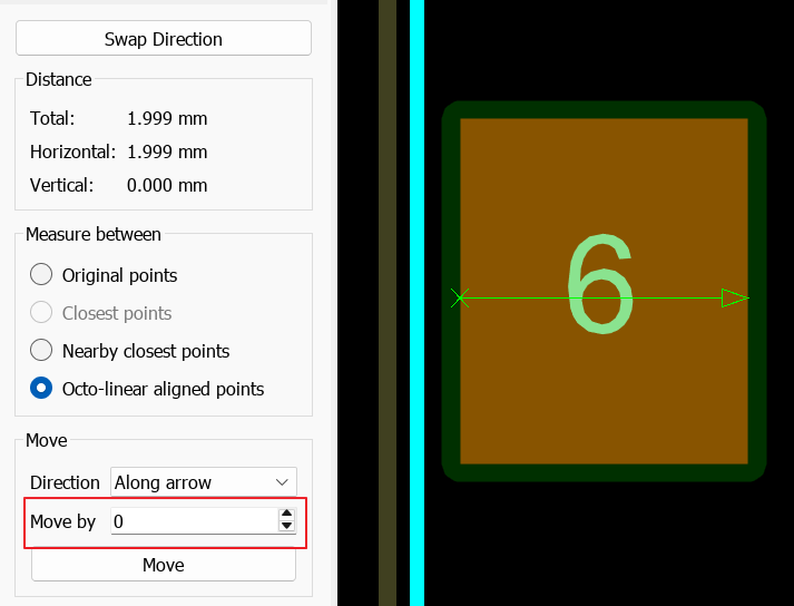
The Move group when both ends of the arrow land on the same object: the New Distance label is replaced by Move By, with a default value of zero. Compare with the Measure Panel image earlier in this topic, which shows the two-object New Distance variant.
The Move function cannot adjust dimensions inside an object. You cannot use Measure Mode to widen the board, change the pitch of pads on a footprint, or alter the internal geometry of any single object. The Move By function offsets the whole object as a rigid body. To change a dimension within an object, edit the source: regenerate the footprint with a different pad pitch, redraw the board outline, or edit the trace.
1) Make a measurement between two points on the same object.
2) In the Move group, choose a direction from the Direction dropdown (Along arrow, Horizontally, or Vertically). The behaviour is the same as for two-object moves.
3) The Move By spin box is pre-populated with zero. Enter the offset you want, in the current board units. A positive value moves the object in the direction of the arrow; a negative value moves it the opposite way. (For Horizontally, positive is to the right; for Vertically, positive is upwards.)
4) Click the Move button. The entire object is offset by the entered amount.
This is useful for nudging a component, footprint, or board feature by a measured amount. For example, you can measure the pitch of two pads on a connector, then offset the whole connector by exactly that pitch to align it with another row of pads on the board.
Complementary Positioning Tools
Measure Mode handles the common measure-then-move workflow directly, but several other tools complement it for more complex positioning tasks:
- Move To: places a selected object at a specific X/Y co-ordinate, or at a defined radius and angle in polar mode. Available from the right click context menu on an object.
- Block Move / Copy / Rotate: operates on multiple objects in a selection box. Block Move allows dragging a group to a new location or using Move To for programmatic positioning.
- Align: automatically lines up selected objects by edges or centres, using object bounds, pad bounds, or pad centres. Available from the Edit Menu or CTRL+A after selection.
- Distribute: evenly spaces selected objects along horizontal or vertical axes, using object bounds, pad bounds, or pad centres. Available from the Edit Menu or CTRL+D after selection.
- Replicate: duplicates a selection at defined step intervals, with selectable reference points and the choice of offset-based or separation-based spacing. Available from the right click context menu or Edit Menu after selection.
For detailed coverage of Replicate, including offset and separation modes, reference point options and radial replication, see Replicate in Block Editing Commands.
Measure Mode moves a single object at a time. When you need to duplicate multiple objects at a defined separation (for example, creating a row of LEDs at a given pitch, or repeating a group of components across the board), Replicate is the better tool. Use Measure Mode to verify the starting position and clearance of the first object, then Replicate to produce the copies. Replicate in Separate mode can space copies by the gap between their physical edges (object extremity, copper extremity, or courtyard), which is directly analogous to the edge-to-edge distances that Measure Mode reports.
False Origin and Measurement
The False Origin command redefines the (0,0) reference point anywhere on the board. While Measure Mode is the primary tool for measuring between objects, the false origin remains useful for co-ordinate-based workflows:
- Setting the origin on a board edge or datum point, then reading absolute co-ordinates from the status bar as you hover over features.
- Using Move To with co-ordinates relative to a known reference, for example placing a fiducial at (3, 3) from a board corner.
- Aligning the grid origin to a specific feature for grid-snapped placement.
For details on false origin usage, co-ordinate systems, and grid snapping, see Co-ordinate Systems.
Best Practice
Use Measure Mode for Edge-to-Edge Checks
Whenever you need to know or control the gap between two objects, use Measure Mode with Nearby Closest Points or Closest Points. This gives you the true edge-to-edge clearance without needing to set a false origin, calculate offsets mentally, or switch to a fine grid.
Choose the Right Measurement Mode
Original Points is best for point-to-point measurements (pad centre to pad centre, vertex to vertex). Nearby Closest Points is best for gap measurements in a specific region. Closest Points gives the absolute minimum clearance. Octo-linear is the right choice for the typical layout case where features are horizontal, vertical, or on the 45° routing grid: it gives clean board-aligned distances and naturally coincides with perpendicular drops in those cases. Reach for Closest Points or Nearby Closest Points instead when working with arbitrary-angle features such as a non-45° chamfered edge or a rotated component.
You can switch measurement modes once the arrow is in position as well.
Check the Arrow Direction Before Moving
Before clicking Move, check which end of the arrow is on the object you want to reposition. When you are zoomed in, it is easy to overlook that the arrow tip is on a large object like the board outline or a power zone. Moving such an object shifts everything associated with it. If the arrow is pointing the wrong way, click Swap Direction first so that the smaller, intended object is at the arrow tip.
Combine with Other Tools for Complex Layouts
Use Measure Mode to verify clearances after using Align, Distribute, or Replicate. For example, replicate a row of components at a known pitch, then use Measure Mode to confirm the edge-to-edge gap meets your mechanical requirements.
Layer Visibility Controls Snap Targets
If you are measuring between objects on a specific layer and the snap keeps finding objects on other layers, hide the unwanted layers before measuring. The snap system only considers visible layers.
See Also: